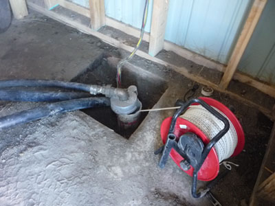
Regular well monitoring is essential for assessing the operation and condition of your well.
As monitoring data is collected over time, informed decisions can be made on scheduling preventative maintenance and repairing or replacing any deficiencies.
On this page:
Water level monitoring
One of the key elements of well monitoring is to record water level measurements on a regular basis. Both non-pumping and pumping water levels should be taken at least a monthly basis. Changes in the non-pumping level or "static" water level may signal possible aquifer depletion, while changes in the pumping level may indicate a possible decline in well performance as a result of screen plugging.
Selection of an appropriate measuring method will usually depend on the well's accessibility, the depth to water and the measurement frequency. To ensure consistency and comparability of water level measurements a measuring point, such as the top of the well casing, must be established and marked on the well and all future measurements must be taken from this point.
Most wells are not easily accessible for water level monitoring, therefore, "user-friendly" well designs are recommended that include an access tube for water level monitoring.
When recording water level measurements the following information should be included:
- Date and time of measurement.
- Time of day; measurement should be taken approximately the same time every day.
- Record the depth of water below a consistent measuring point.
- Identify measuring point and its elevation (distance from ground level).
- Identify any nearby influences, such as nearby pumping wells or cascading water in well.
Water level measurement
The following procedures and devices can be used to measure non-pumping and pumping water levels in a well.
Non-pumping (or static) water level
The best time to measure the static (non-pumping) water level is the when the pump has been resting for quite some time; for instance, early in the morning prior to any water use.
- Ensure that the pump is shut off until the measurement is completed.
- If the pump has been running, wait at least 15 to 30 minutes to allow the water level to recover before taking a measurement; however, in a low permeable aquifer the recovery time may take several hours.
- After taking an initial measurement, wait another 15 to 30 minutes and measure again to ensure that the water level is stable and is actually the static water level.
Pumping water level
The pumping water level is recorded while the well is operating. For comparison purposes, the pumping water level measurements should be taken for pumping periods of the same duration. For example, the pumping water level and the discharge rate can be measured after the pump has been operating for 30 minutes.
Any future measurements should then be taken after 30 minutes pumping. If the discharge rates are the same but the pumping water level has decreased than plugging of the well intake may have occurred.
Electric sounder

The electric sounder is one of the simplest methods for measuring water levels in a well. An electrical sounder consists of two parallel insulated wires with a weight attached to the end. When the wires contact the water the current travels through the water completing the circuit. This contact causes an ammeter, buzzer or light to signal that the circuit has been completed.
The current is supplied by batteries usually housed in the tape reel assembly of the sounder. Commercial units are usually marked with regular intervals so that the depth of water from the top of the casing can be easily determined.
The electric sounder can sometimes be affected by leaks in the pump column. As the sounder is lowered into the well the water leaking from the pump column may cause a premature signal. User-friendly well design can include the installation of an access tube that will keep leaking water from coming in contact with the sounder tape and help to ensure that the tape does not become entangled down the hole.
Sonar water level meters

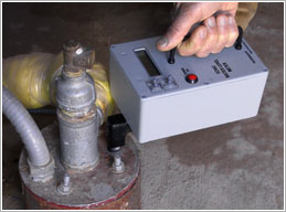
A sonar water level meter uses sound waves to measure water levels and doesn't require the installation of a down-hole probe. Generally, the only requirement is an access port at least 15 mm in diameter in the well cap.
This type of meter is easy to use and provides a direct readout on the display unit of the device. Simply insert the measuring duct through the well cap, push the power-on switch and the measurement is completed in a few seconds.
Electronic pressure transducers

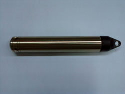
Electronic pressure transducers with data logging capabilities can be installed in a well to record and store water level data. This data can then be periodically downloaded and displayed on a computer to observe the data and potential water level trends.
These devices measure water levels as pressure readings, such as, the height of water above the device. Therefore, at the time of installation, the depth of the device relative to ground level or top of well casing should be measured. However, these devices may not compensate for barometric changes, and therefore, the recorded water levels must be corrected by obtaining local barometric data from a local weather station or by installing a pressure transducer that measures and records changes in atmospheric pressure.
Well performance monitoring
Well performance monitoring is performed to evaluate the well efficiency and to assist in identifying any potential problems. The well, pump and aquifer systems are interrelated, and therefore, it is often difficult to determine the source of the problem when well yield starts to decline.
Deterioration in well yield could be the result of an inefficient pump, plugging of the well intake area, or reduced production from the aquifer. To assist in identifying the onset or cause of yield problems, well performance tests can be conducted periodically to determine if there are any changes in well yield, drawdown (which is the difference between the initial non-pumping water level and the pumping water level at a specified time interval) or overall production of the well over the long-term. The results from these tests are then compared to the baseline data recorded when the well was first installed. If this baseline data is not available, periodic testing should commence immediately to accumulate data for future comparison.
Well performance tests
Pump tests will only provide reliable data if carried out systematically, and accurately recording time, discharge rate and drawdown measurements. The length of a pump test will generally depend on the type of test performed, the type of aquifer, the resources available and any site limitations.
Prior to conducting a pumping test the following should be carried out or determined:
- Maximum drawdown available
- The discharge rate(s) and best way to measure
- Best method to accurately measure water levels and time intervals
- Suitable length of pump test
- Disconnect pump from pressure storage tank and treatment systems
- Ensure water is discharged a safe distance to prevent re-circulation
- Potential interference effects, such as near by surface water bodies, aquifer boundaries, and other pumping wells
The main well performance tests are the step-drawdown test and specific capacity test.
Step drawdown test
A step drawdown test is often used to assess the performance of a well. In this test, the well is pumped at successively higher pumping rates, and the total drawdown at each rate is recorded. Usually, three to five pumping steps are performed. The time interval for each step is the same and the discharge rate at each step must remain constant. A valve set-up is necessary to vary the discharge rate and an appropriate method to measure the discharge would be required, such as a flow meter or calibrated pail.
From these test results, the well efficiency, drawdown and specific capacity can be determined at a given pumping rate.
Since this test involves pumping the well at various discharge rates it may not always be possible for an individual well owner to perform, therefore, the specific capacity test would generally be more practical.
Specific capacity test
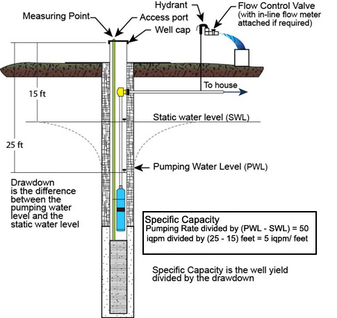
Specific Capacity is an assessment of the productivity of the well, and is defined as the well yield per unit drawdown (Imperial gallons per minute/foot (Igpm/ft) of drawdown). This translates into the amount of water level drop in a well at a designated pumping rate, over a specific time interval.
A general specific capacity measurement can be calculated using the maximum and minimum (non-pumping and pumping) water levels collected over a designated time interval. For future comparison purposes, these water levels should be collected over similar time intervals, with the same pumping rate.
A more accurate measurement of specific capacity can be made by conducting a pump test to determine any changes in the well's capacity. These tests should be conducted at least twice a year. When conducted in different seasons, they may also indicate if there are any seasonal fluctuations in the specific capacity of the well.
Pump tests to measure the specific capacity and overall well performance should also be conducted prior to any anticipated groundwater development or exploration activity in your area. This includes new commercial developments, irrigation well development, and drilling activity by the petroleum industry.
To calculate the Specific Capacity of your water well follow these steps:
- Allow the water level in your well to recover to its highest point. The best way to do this is to shut off the pump at night and perform the test early in the morning.
- In the morning, measure the water level in the well to ensure that it has stabilized and is not rising in the casing.
- Start the pump.
- Record the water level at five minute intervals.
- Measure the pumping rate (rate of discharge) at the beginning and near the end of the test.
- Run the test for a designated amount of time (30 minutes or one hour).
Specific capacity calculation
Record:
- Pumping Rate.
- Static (non-pumping) water level at start of test (SWL).
- Pumping Water level at end of test (PWL).
- Note time duration of test.
Calculation:
Pumping rate in (Imperial gallons per minute) ÷ (PWL - SWL (feet))
See example below:

Description of the image above
Figure illustrates the calculation of Specific Capacity. Specific Capacity is the well yield divided by the drawdown. The difference between the Measuring Point above the well surface and the Static Water Level is shown as 15 feet. Drawdown is the difference between the pumping water level and the static water level. The measured static water level is shown as 25 feet. The pumping rate was measured as 50 imperial gallons per minute. Therefore the Specific Capacity is 50/(25-15)=5 imperial gallons per minute/foot.
Water quality monitoring
Regular monitoring should be conducted to ensure a safe and healthy water well supply. Groundwater contains natural chemical constituents that are derived from the soil and rock materials that the water passes through. Although not generally harmful to human health, these chemical constituents can sometimes consist of potentially harmful parameters like arsenic, selenium, boron or radon that may present health problems depending on the concentration present.
Besides natural chemical constituents, groundwater can become contaminated from nearby agricultural or human activities such as improper storage of wastes or agricultural chemicals, animal manure storage, poorly maintained septic systems, leaking underground storage tanks and accidental spills.
Understanding and identifying any potential problems early is essential to safe-guarding a groundwater supply. A well owner should have a water quality analysis performed when the well is initially constructed and then test the water at least once a year for any microbiological contamination and any water quality parameters of concern identified in the original analysis.
Additional water quality monitoring should be considered if there is a change in land use activity nearby, flooding of the well or an accidental spill the vicinity of the well. Also, a change in colour, taste and odour of the water may also indicate a change in water chemistry or bacteriological quality.
Monitoring checklist
To facilitate a systematic monitoring approach, a well monitoring and maintenance checklist can be developed. There are many items that can be included on a checklist as outlined below, and a well owner can adapt these to their particular situation and adjust the monitoring intervals accordingly. Examples of items that can be included on a monitoring/maintenance checklist are as follows:
- General Physical Inspection
- ensure the well cap is secure and the well vents are unobstructed and screened to prevent pests/insects from entering the well
- ensure the well seal around the casing is in place and water-tight
- note any changes in turbidity, taste, odour and colour of the water
- ensure the ground is not settling around the casing allowing surface water to pond
- inspect the outside and inside condition of the well casing
- check for additional pumping wells in the area that may cause interference effects
- check operation of pressure tank and water treatment system
- record the date and time of the inspection and any observations
- Monitoring
- date and time, note any changes to static water level, pumping water level, pumping rate
- collect and record operational data (hours of pumping, discharge rates)
- note any changes in in-take pump voltage and amperage readings
- conduct a well pumping test to measure the specific capacity of the well
- test water for bacteria at least two to four times a year
- test any water quality parameters of concern, such as nitrate, chlorine, sodium, iron, and manganese
- test for other chemicals if you have concerns with fuel spills, etc.
- ensure backflow prevention devices are in place and functioning
- Protection from Contamination
- maintain at least a three-metre grassed buffer around the well
- ensure potential contamination sources are located down gradient of the well
- avoid chemical applications (pesticides, fertilizers) around the well
- locate and plug any nearby abandoned wells or test holes
Once a scheduled monitoring program has been in place for awhile, sufficient data should be available to establish a suitable repair or replacement interval for components in the well and distribution system and to develop a preventative maintenance treatment schedule.